How to install Wagenswest 'Beef Cake' Bus beam adjusters,in a Volkswagen bus front axle beam.
Wagenswest beam adjusters originated out of desperation, a desperate search to find an affordable adjuster that would not slip or break under the weight of a Volkswagen bus. Eventually we found teeth that would work well, after that we designed a forged cap to match. Years later we now have the Wagenswest Beefcake beam adjuster, it worked, and happy; we have had zero adjuster fails.
On the other hand, over the years we have seen many failed bus adjusters brought into the shop from other companies, the 3 major reasons for failure are as follows -- not sharp enough teeth, no way to tighten the bolt tight enough and no relief slot in the spring retainer boss for expansion in the tube (slots are best used in new narrowed beams), the slot is to eliminate wobble and the following metal fatigue from too loose of a spring boss.
So for the above reasons, we continue to use a large adjuster bolt and big adjuster teeth.
2 obstacles of the large bolt is as follows – on the 1963-67 bus, the bottom adjuster bolt can interfere with the damper, when adjusted low. The second interference comes from the top adjuster on all year buses, when adjusted to stock height the bolt will hit the shift rod.
The following how-to or “instructions” will help explain how to install the adjusters and how we overcome the two obstacles.
Each step has a coinciding photo that can be found further down in this article.
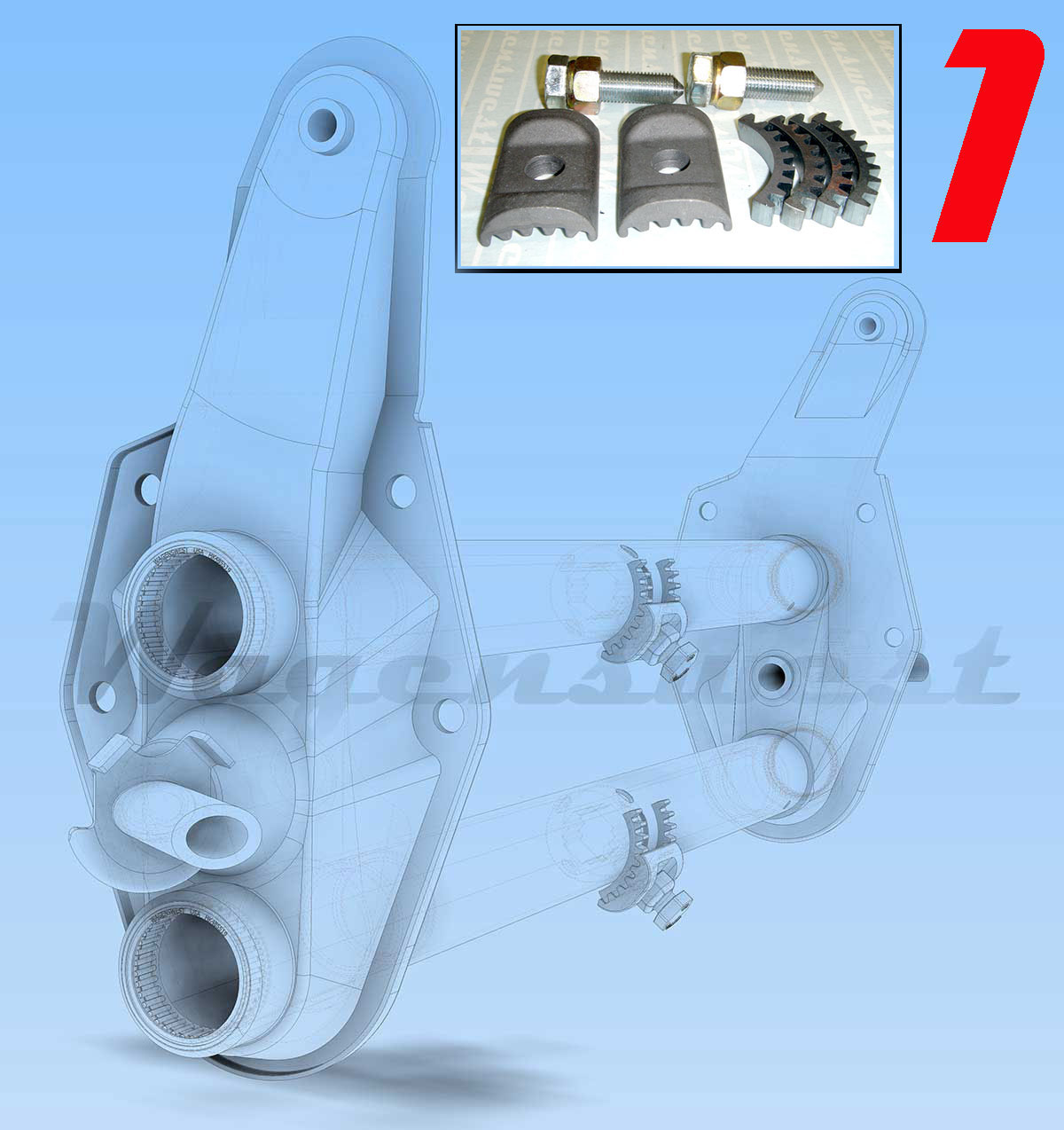
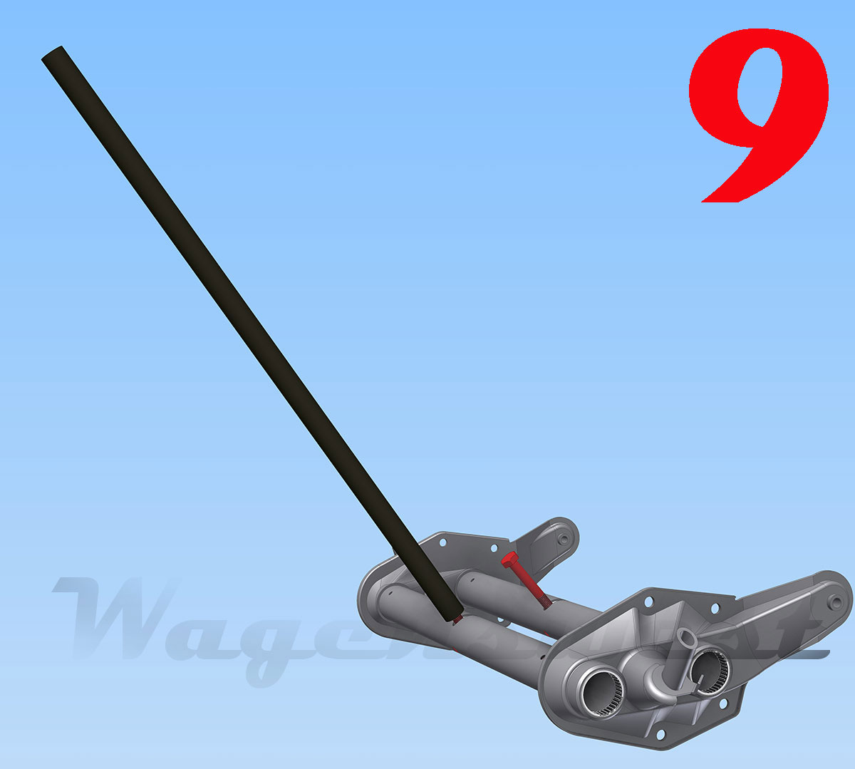
Step 1
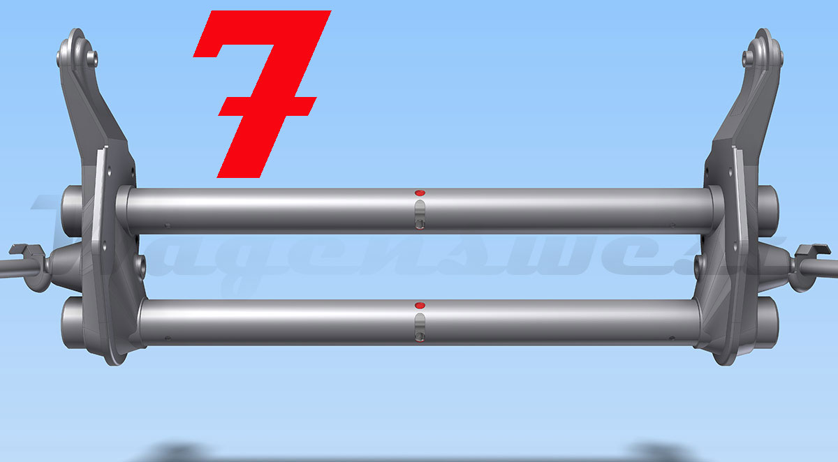
Get ready; know what you are in for.
This photo shows a split window Volkswagen bus beam with Wagenswest adjusters installed, the adjuster bolts are at the stock height position. Notice that the swing lever box is removed, in order to install adjusters on a Bus beam, you will need to grind the welds and remove the swing lever or center pin box. You will need to drill out the 6 locking dimples, 3 on each beam tube, two of which are blocked by the center pin housing --- this is reason we need to remove the pin box.
After the box is removed we will drill-out the 6 locking dimples, after this we will need to cut a 9/16 wide slot, from the center of the grub nut hole to 1” inch up at the center of a new hole you have drilled with the 9/16 drill bit. After this we need to break the spring bosses lose in the beam tube, once the bosses are freed up enough we can line up and weld on the adjuster teeth. We will finish up the job by re-aligning and welding the center pin box back on.
Tools needed
Hand tools and jack stands, sufficient tools to remove the beam from the bus, brakes, spindles, tie rods, swing lever and probably the trailing arms and torsion springs need to come off to do a nice job.
- A - MIG or maybe a TIG welder or if you like it old school, an oxy/acetylene welder will even work.
- An - angle grinder or pneumatic cut off saw.
- A – Hammer.
- A – Center punch.
- Two - 14mm x 100mm sacrificial bolts, these are to break the stock centers loose.
- A - 9/16 drill bit and ½ inch drill.
- A –Tape measure.
- A – Sharpie marker.
- A – Breaker Bar.
- A – 14mm x 1.5mm Tap, in case you need to clean up the spring boss threads.
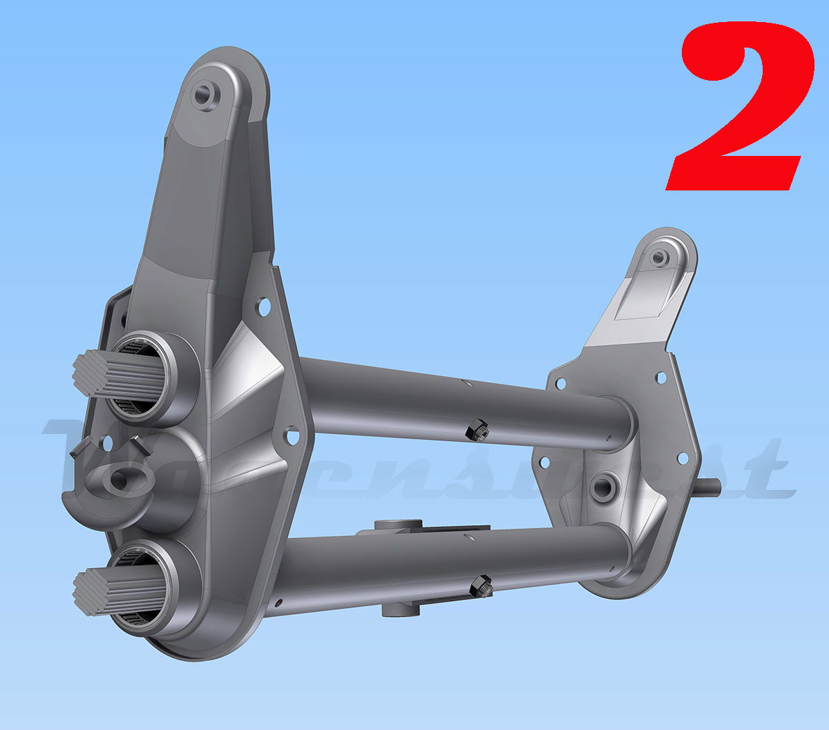
Step 2
Notice the grub nut set screws and torsion spring packs.
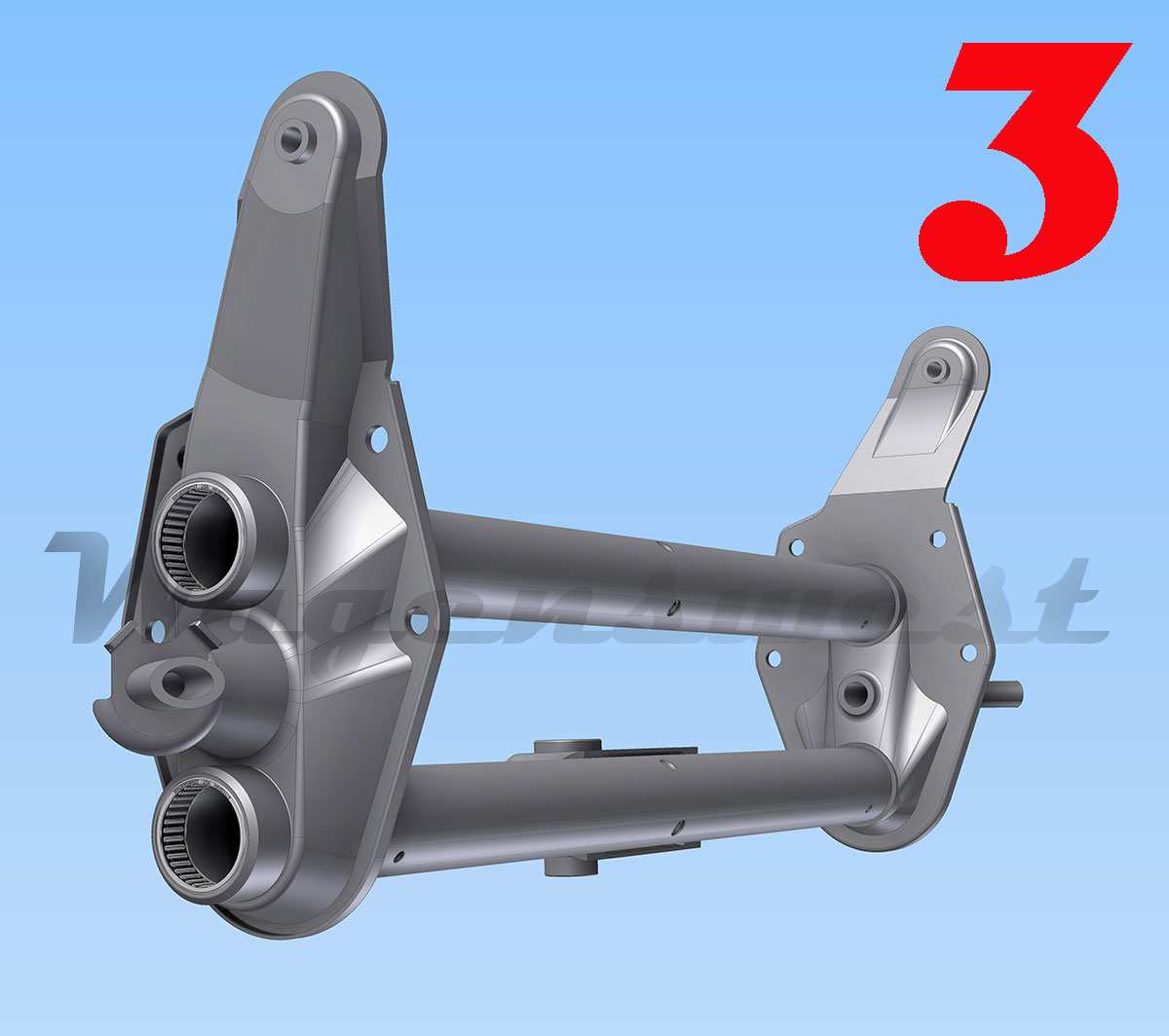
Step3
Remove the grub nut set screws and torsion springs.
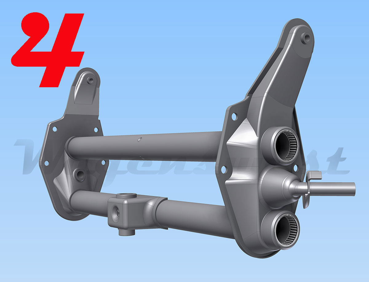
Step 4
Notice the swing lever/center pin box, find the welds around the perimeter and grind them off.
Step 5
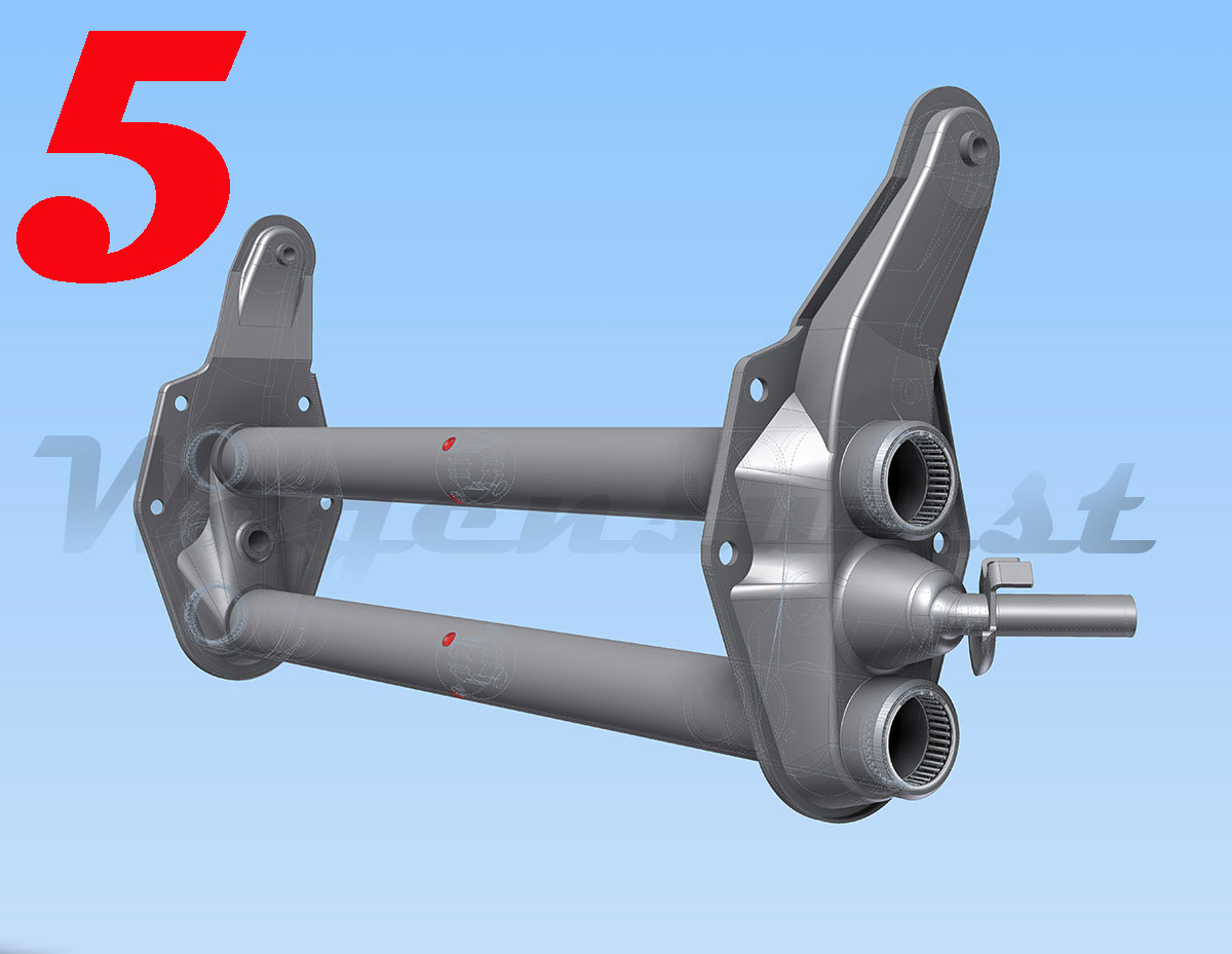
Find the 6 locking dimples, 3 on each tube, painted red in the photos. Spot drill these out with the 9/16 drill bit.
Step 6
This is what the spring bosses look like; these are what you are trying to loosen up. They keep your torsion springs locked in place.
Step 7
Slotting; measure from the center of the existing set screw holes, up 1”inch place a dot with a sharpie marker, then use the center punch and hammer to make your mark. Do this on both tubes and make sure these punched holes are good and centered; you will use them to guide your drill bit. Now using the 9/16” drill bit, drill out the two punch marks, just deep enough to make a 9/16 hole in the tube wall only. Don’t go too deep!
After you have the two holes, you will need to use a cutting wheel to cut away the metal in-between the two holes finishing the slot, a pneumatic high speed rotary cutter works best (15.00 at harbor freight).
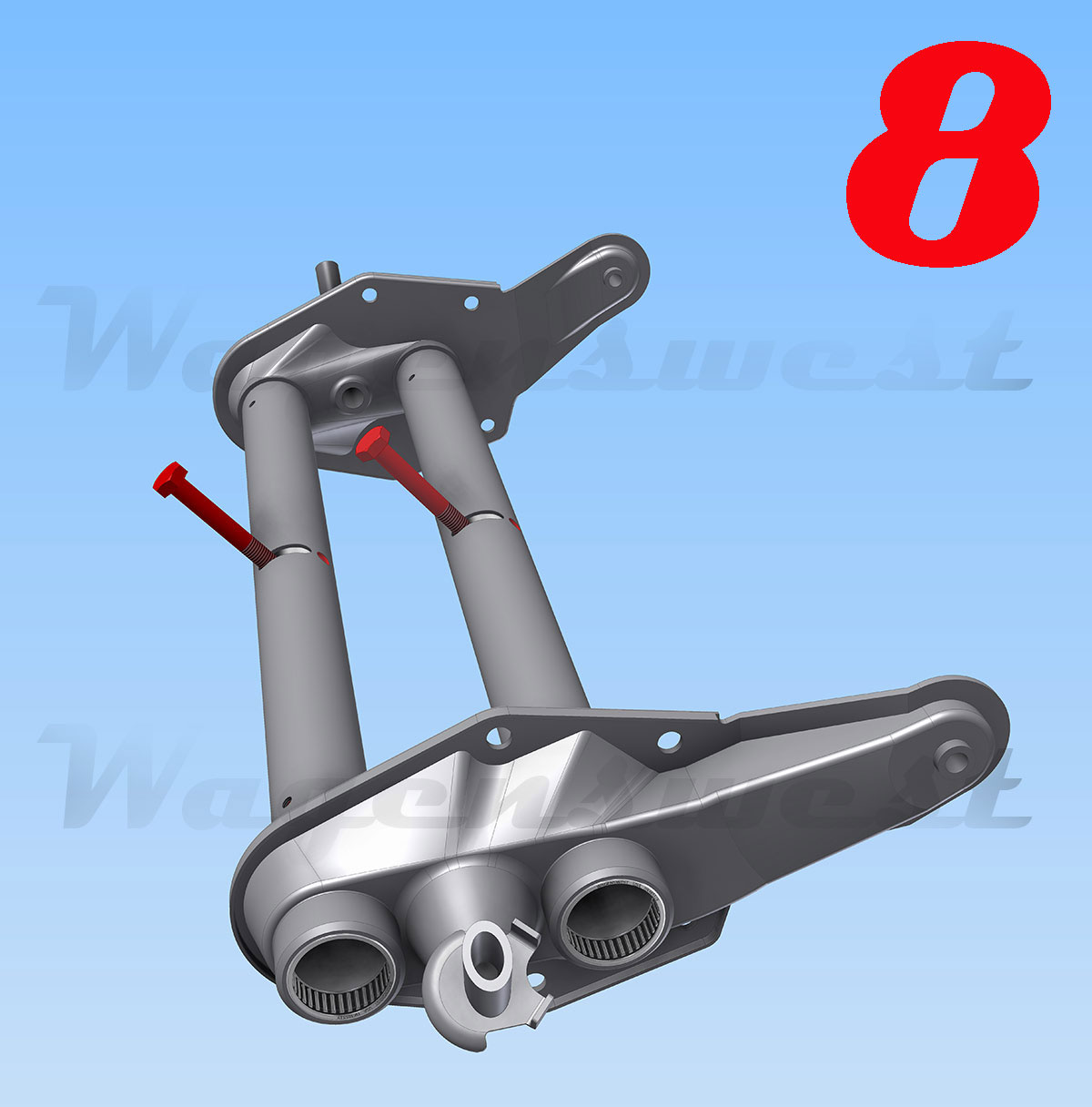
Step 8
Now that you have adjuster slots, insert the sacrificial 14x1.5mm x 100mm bolts.
Step 9
Slide a breaker bar or something like it over the bolts, start to gently free the center blocks. Tapping around the tube kindly with a hammer will help loosen the center blocks in the tubing.
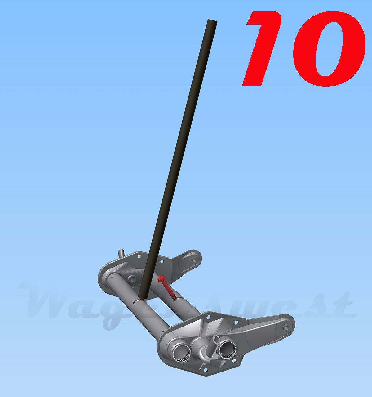
Step 10
Be patient, freeing these blocks can take time.
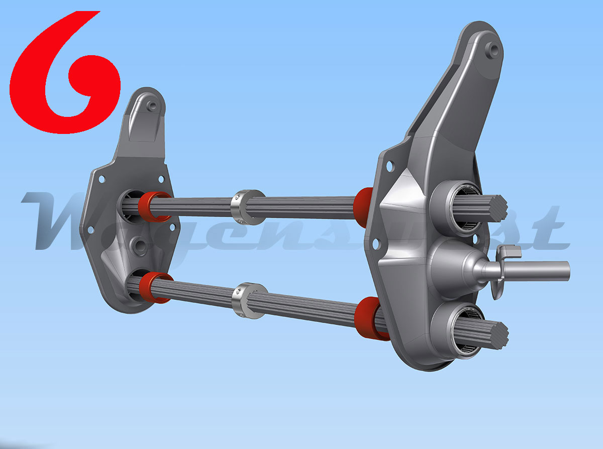
Step 11
Now that you finally have the center blocks moving, it is time to line up the adjusters. Using the adjuster caps to position the teeth, with the cap hanging over one tooth on the bottom (see photo 12), center the cap’s bolt hole with the beams original set screw/grub nut hole and spring boss hole.
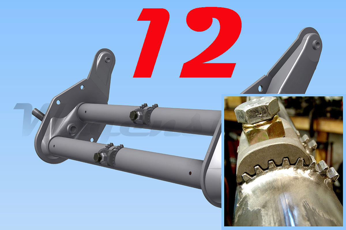
Step 12
After aligning the cap and the teeth together in the original stock position with the spring boss, insert the adjuster bolt. It’s now time to tack-weld, then check the alignment; after you are sure the teeth are straight you can weld the adjuster teeth to the beam tubes. Weld the outside of the teeth first, then remove the caps and bolts and weld the inside of the teeth. Make sure that your welds are small and hot with good penetration.
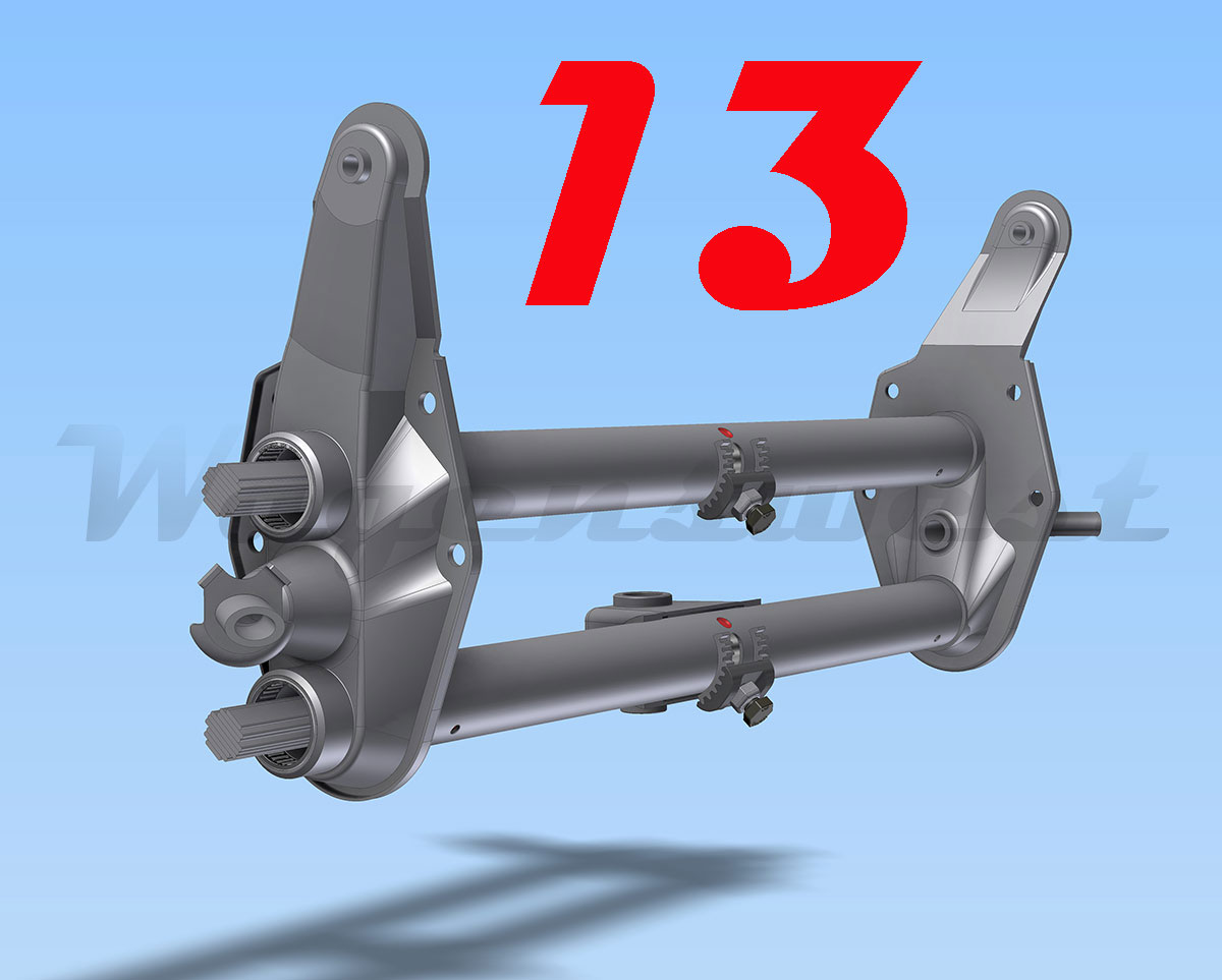
Step 13
Re-align your swing lever/center pin box and weld it back on. The center pin box should sit exactly centered in-between the beam’s side plates. The center pin shaft should be 180.” Degrees across the beam tubes looking up or straight to the sky with the beam sitting up right.
After welding the adjuster teeth on, it is time to cut the top tube and rotate the top adjuster to the front of the beam (see step 16, 17, 18) or put the beam all back together and install it in the bus (see step 14, 15 for damper offset).
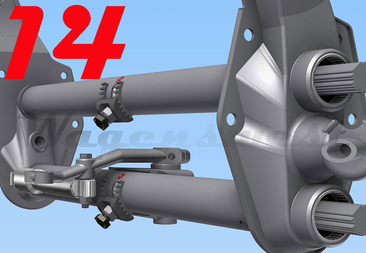
Step 14
Photo 14, shows how the adjuster bolt can interfere with the damper on 1963-67 bus beams.
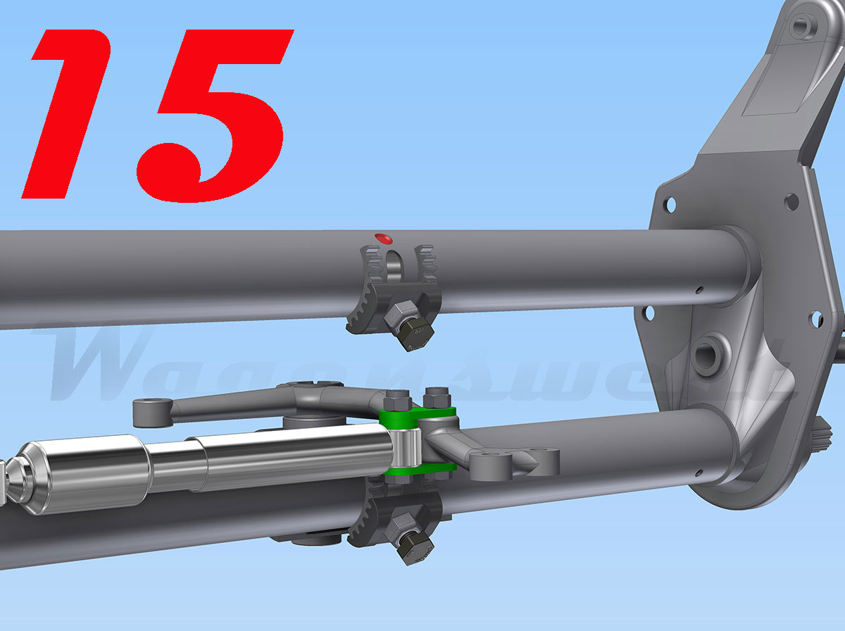
Step 15
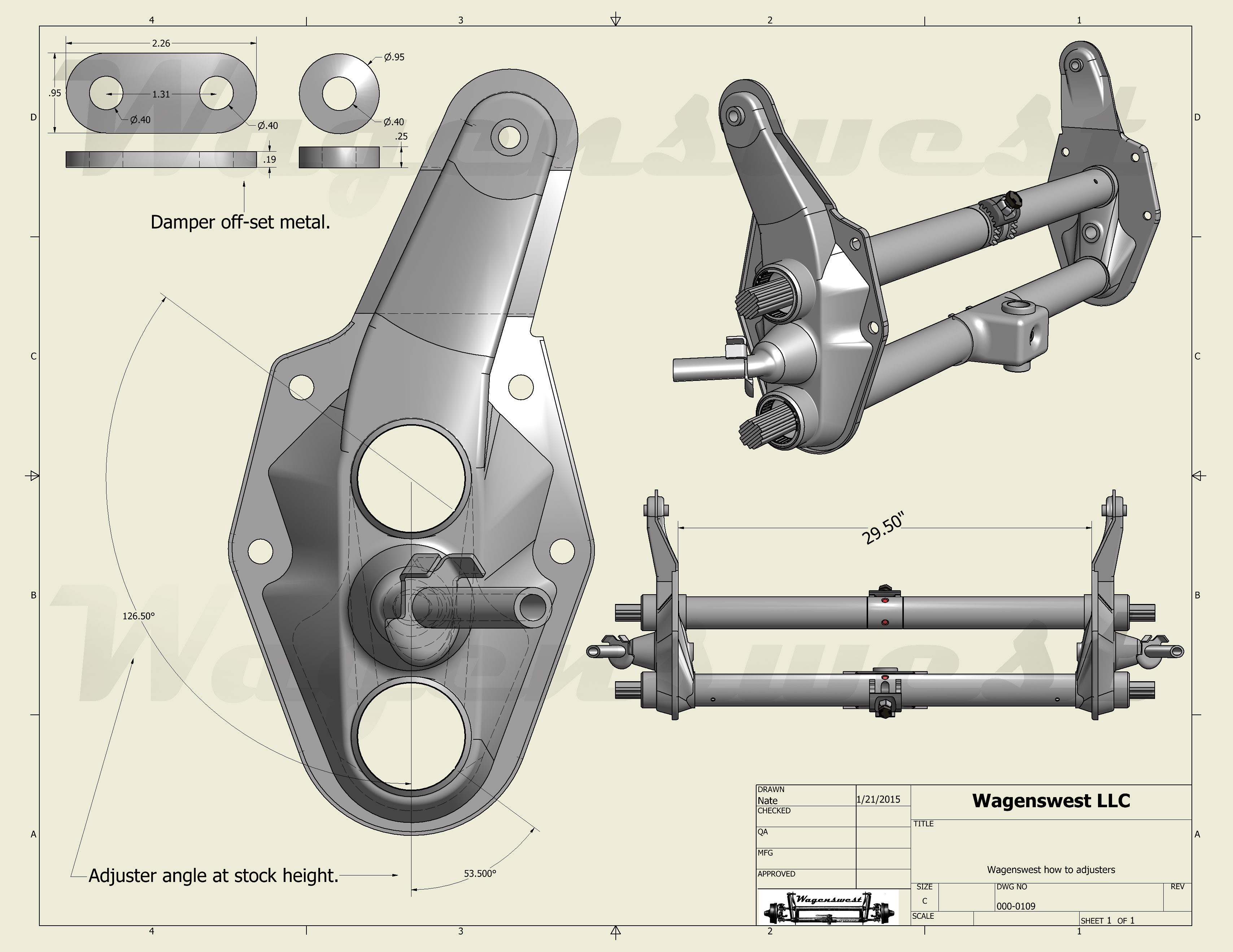
Photo 15, shows a damper offset. To get around this damper interference, we have made a damper off set bracket; we use these on all of our narrowed split beams that use the 1963-67 swing levers. These damper offsets can be made using the blue print in this how-to or we do sell them.
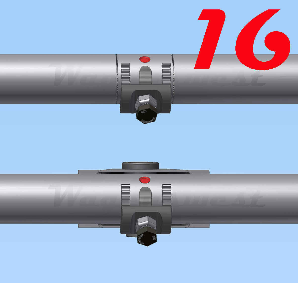
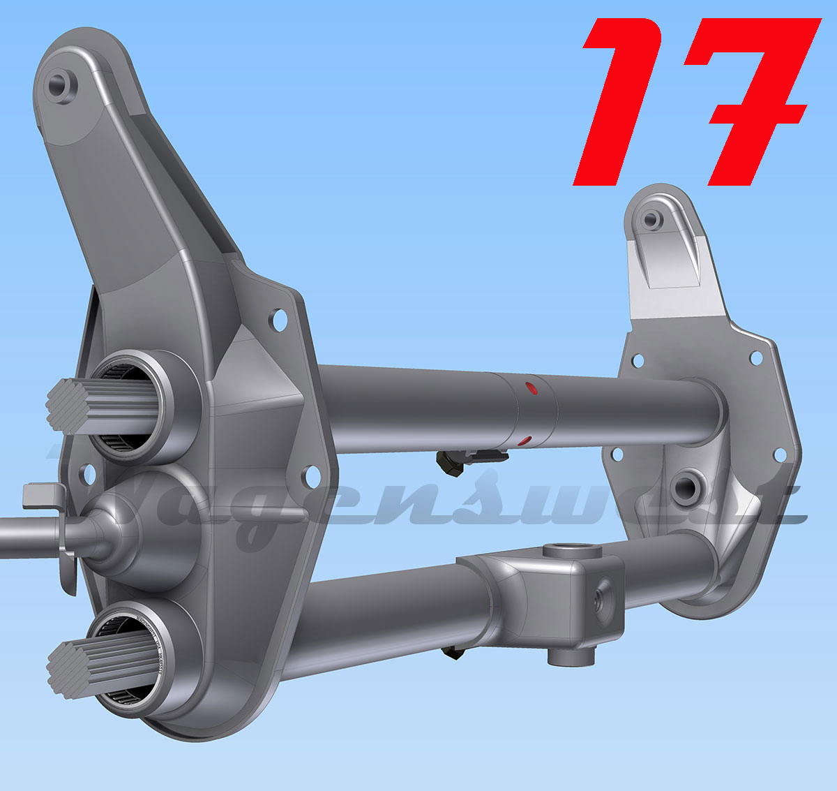
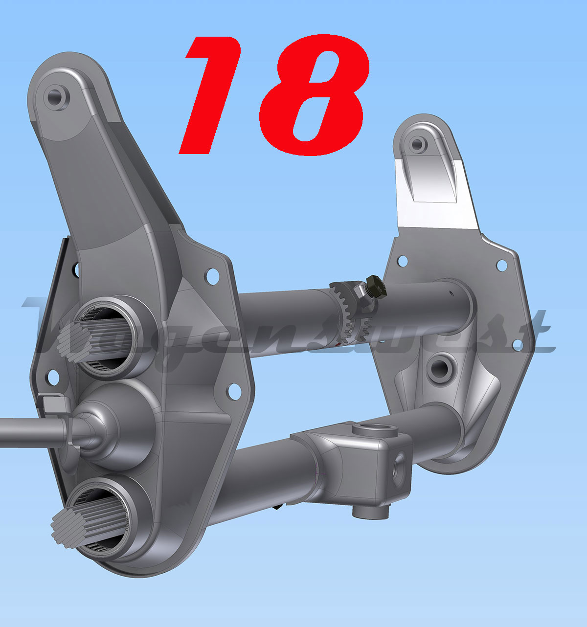
Step 16, 17
If you think you will ever need to set your beam adjusters near stock height. We suggest putting the top adjuster on the front side of the beam. This is done by carefully cutting the top tube on each side of the adjuster and rotating the top adjuster 180.0” degrees to the front of the beam and re-welding the beam tube. We build all of our narrowed beams this way. If you do move the adjuster to the front, you will also need to dimple the spring pack on the back side, in order to lock it down with the adjuster bolt in this new position. Keep an eye on the width between the side plates so it stays at 29.5”inches when welding the tube back together.
Step 18
Photo 18, shows the top adjuster in the front, in the stock height position with adjuster slot now facing down.
In conclusion
Beam adjusters are best used in conjunction with dropped spindles, for a smooth ride. Putting adjusters in a stock beam can be a lot of work; it is also very worth it when you need to fine-tune your ride height.