Installing 1955-67 flipped bus spindles.
When installing flipped dropped spindles for early buses there is always some confusion, it is usually because the king pin now needs to be rotated 180 degrees from stock, the spindle itself will stay in the same position.
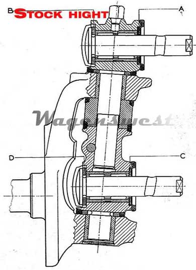
It is the kingpin that is now inverted up side down in the spindle (refer to image B).
So when the king pin gets flipped it must also be rotated 180 degrees in order to maintain properly positioned link pins and caster offset.
Here are a few things to help you install your dropped spindles.
Of course you will need to remove the stock spindles drums brakes ECT Refer to a Bentley manual.
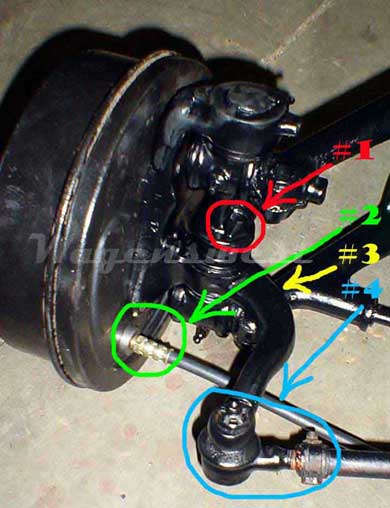
Looking at image image (A)
#1 the king pin locking bolt needs to be on the bus side of the king pin.
#2 the brake line must now be at the bottom of the backing plate, so this means you must rotate your backing plate up side down.
(No need to remove and reinstall break components just rotate the backing plate).
#3 All Wagenswest flipped dropped spindles have inverted tie rod tapers that are a larger taper in order to fit post 69 tie rod ends. (The tie rod ends Install upside down)
Refer to image (B)
In this image you will see a diagram of a stock spindle and if you touch it with your pointer it will rollover and show you a drop spindle diagram.
In this image A, B, C and D Arrows are pointing at shims in-between each side of the link pins. These shims are used to help the link pins move with less friction and to fill up any difference in the off set of the trailing arm position verses the king pins position.
(These shims are not intended to set or adjust the camber; camber/caster is preset from the factory if your camber is off you probably have a bigger problem).
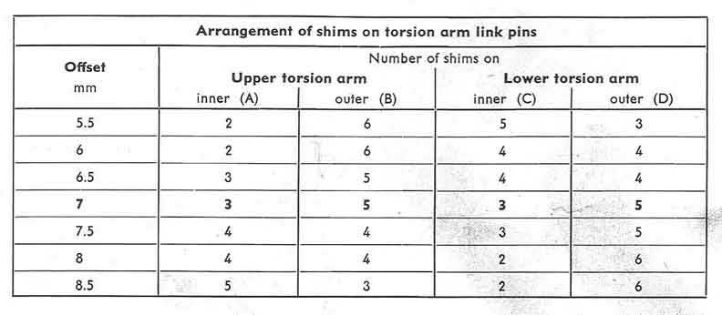
Refer to image (C)
This image shows you the amount of spacer shims needed to properly mate your spindles to the trailing arms.
You will first need to measure how much more the bottom trailing arm protrudes from the beam than the top one it is usually 3 -8 mm more than the top.
You can usually measure this with a straight ruler laid across the bottom trailing arm shim surface pointing up over the top trailing arm shim surface.
You can use image (B) in correlation with image (C) to determine the amount of shims needed.